 click on pictures to enlarge |
Figures: Primary Mirror (self made): Total weight: Finder: |
[ Home ]
click on pictures to enlarge |
Figures: Primary Mirror (self made): Total weight: Finder: |
Optic:
The primary mirror is made by myself. When in August, 2002 my 14” mirror broke on the tiles due to weak rack mounting (see picture) it was not possible to get a new blank by return. Therefore I decided to buy an available 315mm blank to eliminate frustrations. After 5 weeks I set it aside (I got some scratches while polishing and had to go back to fine grinding), at this time the successor blank for the 14” project arrives me, it had priority to be finished. At Dec., 26th I continued with the 315mm blank. Two weeks later the mirror was figured, experiences I made with the second 14” helped a lot.
As usual I wrote a diary of the whole grinding, polishing and figuring process, it is approx. 9 pages long but unfortunately in my native language – German.
At the ITV2003 (Germans largest amateur astronomy meeting) I gave the mirror Wolfgang Rohr, a well experienced and equipped guy who tested the mirror with various methods (e.g. interferometry). Result: very good correction, the surface is a bit bumpy, all in all a good mirror.
You can find the diary here (German).
What to do with the mirror? Actually I’ve enough telescopes. Meanwhile I planned to sell the mirror, but for much lower than the price of a 12” Oldham UK plate mirror I was not willing to give it out of my hands. As I had some remaining stuff from building my 20” telescope and enough time during Christmas holydays I decided to build an other telescope.
Mechanical Components:
I was Inspired by Albert Highe's extraordinary 3 trusses dobson designs.
 click on pictures to enlarge |
Primary
mirror cell: Support points are calculated with PLOPP. The 6-point design gave better results than a 9 point design. My plan is to glue the mirror with silicon blobs on the bars, making this there is no further need for assurance bolts. |
|
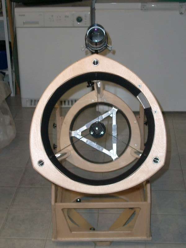
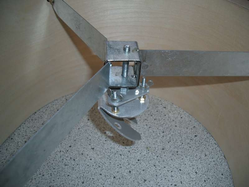
Secondary mirror unit: I took a 3-arms design for the spider, knowing this will cause 6 spikes, but these will be smaller. The arms are made of 1,2”*0.03” metal sheet. In the middle there is a 1,2” piece of a square-pipe tube with treated hole , approx. 3mm(0,12”) offset included. The 66mm (2,6”) diagonal is silicone glued with 3 blobs of 2 mm (1/10") thickness directly onto to the diagonal al-sheet. The 3rd spider arm is soldered in a sawed small placket
|
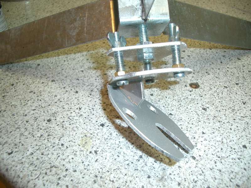 |
The Secondary holder is made of 0.08“ (2mm) al-metal sheet, all parts were cut with a simple mechanical fret saw. To enforce the bent holder, a small metal triangle was glued in. Collimation will be done without any tools, just turn at the butterfly nuts. |
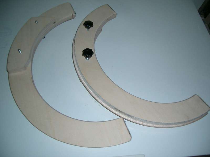 |
Altitude bearing: Radius of the bearings is 20“. I made it with a cheap router. Material: 21mm (0,8”) thick made of Baltic birch plywood. The slide is made of 1mm (0,04”) aluminum. To fix the bearings on the Rocker box, the bearings have a small “lip” (0.2” or 5mm) at the inner side. To increase stability and to reach the necessary distance to the mirror cell 21mm (0,8”) thick plywood was glued inside the bearings.
|
 |
Upper cage: Height is 8“ (20cm); why? I had some remaining aluminum tube (0.8”*0.04” or 20mm*1mm) in this length. The rings were made with the router, too. I connected the rings with the tubes by drilling 0,8” (20mm) holes and gluing the tubes with Epoxi. The cage is covered with 1mm (0,04”) airplane plywood, this increases the stiffness dramatically. The airplane plywood is covered with black velour bonding sheet. The 3 big tubes will be clamped with sawed (mechanical fret saw) wooden blocks. When getting the already ordered bicycle quick release skewers these will be used in future. 3 times “Click” – ready!
|
 |
Lower Tube
clamping: The 3 tubes will be treated trough the upper ring of the mirror box, then it will be put in the notch in the lower ring. This notch is bevelled, with 1,5“ (38mm) outer and 1,35“ (34mm) inner diameter. Just a small turning and the Tubes are fixed – really stable. The upper ring of the mirror box has 3 clamp blocks. Again. 3 times “Click” – ready!
|
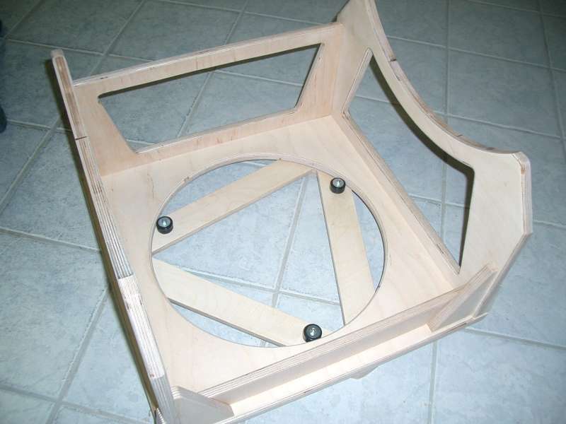 |
Rocker: Similar made as at PHOENIX and URSUS; lots of wood was cut out to reduce weight in areas, there it does not major support stability. In the rear area I built in additionally stiffeners.
|
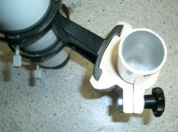 |
Finder mount: I love my mechanical fret saw! With some experience it is possible to make relatively difficult parts. Two pieces of 0.72” (18mm) plywood a carrying the finder shoe. Just attaching it on the pieces I is fixed. The clamping will be done with one M6-star handle; it will be substituted by – no question – a quick release skewer.
|
 |
Mirror
cell: Both rings are connected at the side and the top with 0.5” (12mm) plywood. Additional stability will be reached by gluing 0,06” (1,5mm) airplane plywood. My piece of plywood was cut with the grain along, it took lots of effort to bring it in the right shape using steam, belts and other things. |
|
|
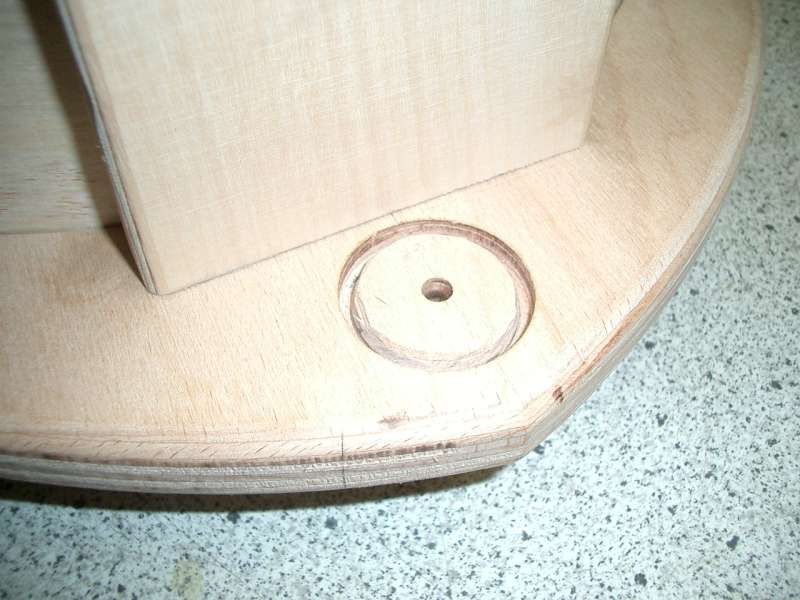
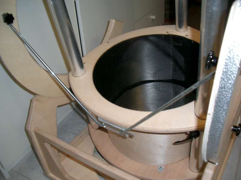
Van:First experience shows, that (at least in winter time) it is not enough to place the mirror box 1hour before observation before the door. Looking at defocussed star you still can see strong wafting, images will be worsen. When the mirror reaches eliquilibrium, the images are much better, but this can last an other two hours. To increase the cooling down I mountend a 9cm (3 1/2 inch) PC van at the bottom, using 2mm (0.08 inch) aluminium. The connection to the power station is via a chinch socket. For the mounting 4 tapping screws were used. |
|
|
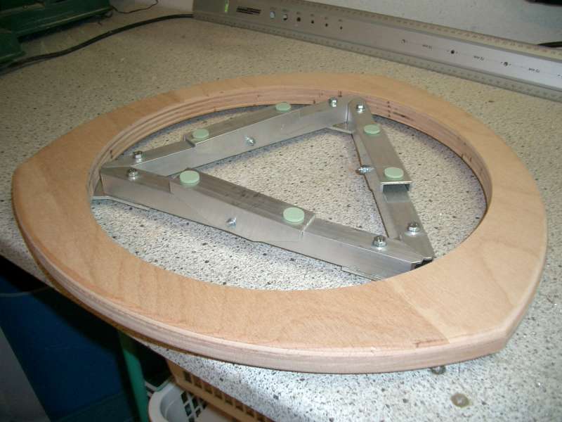
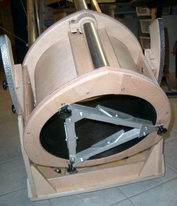
Supporting Triangle for Altitude Bearings:As I've to learn, the long protusive altitude bearings were not stiff enough without additional support, leading to vibrations, annoying observations at 150+ magnification. I adopted the same method as already used at the 20inch URSUS. Sawed off pieces form "IKEA-struts" for shelfs were bended in a bench vice, radius aprox. 1/2 inch at one end. I glued a angle palate at the mirror cell, the stunts will be put through and screwed with a star handle at the altitude bearings. Using brace are made of 3mm (approx. 0.125 inch) aluminium sheet, it become absoluteley free of any tolerance. Monting is very easy and fast: only two times screwing, one time "click", ready!. |
|
|
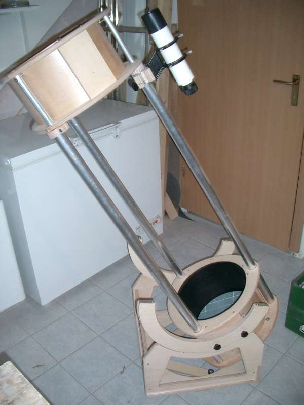
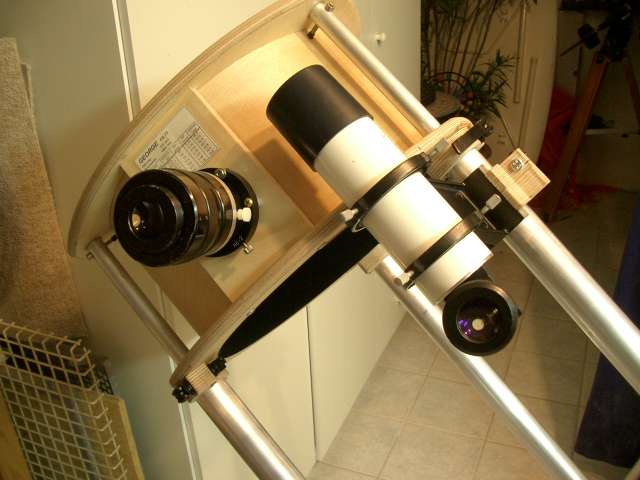
90 degrees Finder:Due to the fact using altitude bearings with big diameter the balance point ot the telescope is relatively high. This allowes to use heavy eyepieces and a relatively heavy finder close to the upper cage. A friend of mine (having the neccessary equipment) made from my 8*50 TAL-finder a 90-degrees-finder, using a amici-prism. Now I can see images erected and true-sided. From the eyepiece to the finder ocular I've to move the head only approx. 8 inches. It is not neccessary to turn the head, my neck is loving this! The finder can be moved on the 38mm (1.5 inch) strunt up and down as I want. For clamping I'm using a quick release clamp. |
Set up:
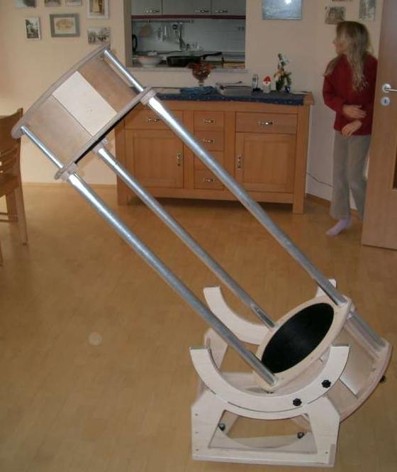
Putting the mirror box on the rocker box, treating the 3 trusses, attaching the secondary cage, 6 times click – ready! All is done in less than two minutes.
To avoid any clearance the clamping blocks of the secondary cage are not mounted directly above the blocks of the mirror cell. They are mounted approx 0.2” (5mm) more inside, this results a kind of initial tension. No problems with attaching of the secondary cage, without closing the clamps there is no clearance at all.
Grey is all theory, the 1st light will show whether the mounting will hold collimation.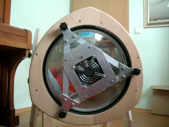